
Subunits:
The problem with my drive was a blocked drum (does not spin up while
POST after reset of the controller).
It was not an electrical problem, because rotating the drum manually,
even with medium force, was not possible too.
This page contains some pictures and hints how to disassemble the drive (some steps are not obvious if you do it for the first time).
I have used the following tools:

(Click to enlarge)
Try to not touch any surface that has direct contact to the tape.
If this has happened use Isopropanol to clean the surface.
The tissue must leave no fluff on the surface.
If you want to clean the drum, be very careful to not touch the heads.
Use a magnifying glass for the regions near the heads.
Never clean the heads manually, use a cleaning tape for them.
This section shows how to generally disassemble the drive into its
main units (so that the parts become accessible).
Separate sections exist how to disassemble the drum subunit, the
capstan motor subunit, and the reel motor subunit.
I have used a white table for disassembly (small parts are clearly
visible).
Placing all removed parts in groups (together with its screws) from
left to right on the table makes it easy to reassemble them in the
correct order (and find the screws associated with each part).
First remove mechanical adapters for mounting the drive in a 5.25" slot. Then remove the front bezel (two plastic clips on the sides).
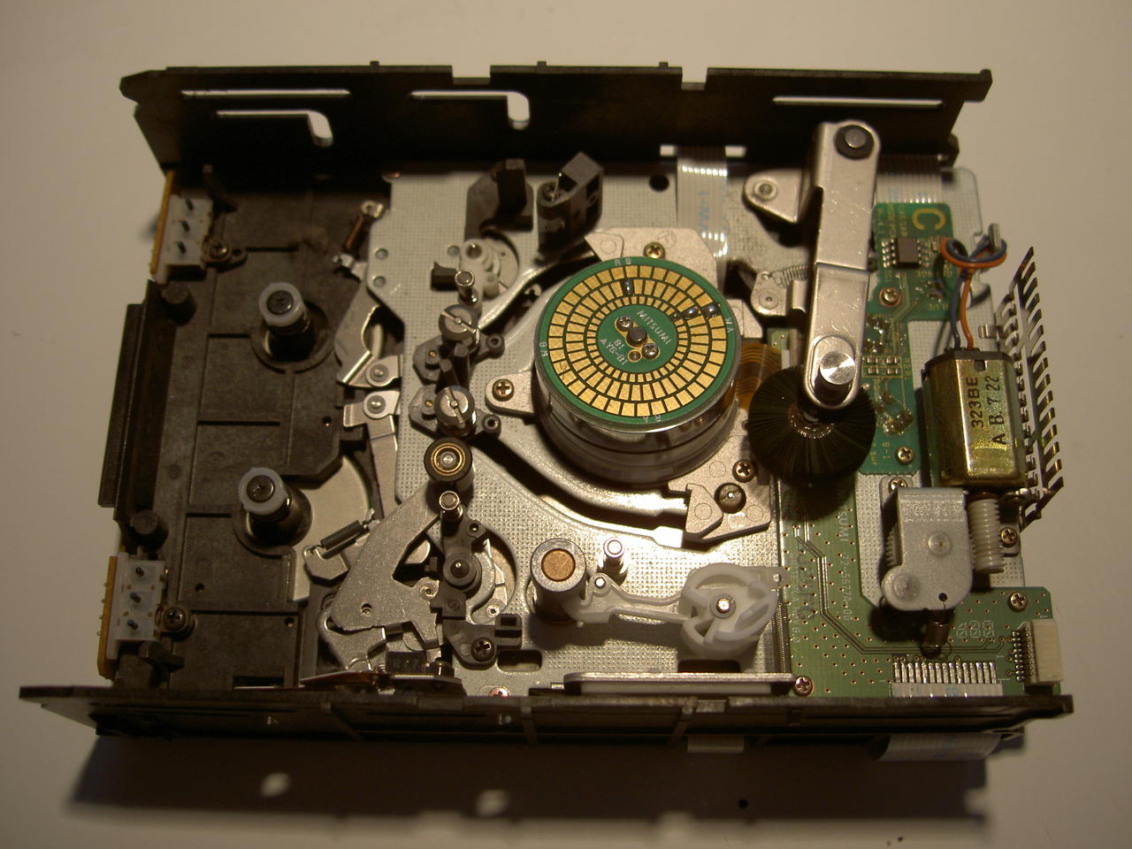
The top cover can be removed without tools: Lift it on the front and
remove it backwards. Now the piece of hardware in front of you should
look like this:

(Click to enlarge)
Now remove the two large Torx screws on the bottom side. To remove the bottom cover, lift it on the rear and remove it in forward direction.
Now open all foil cable connectors on the controller and remove the
controller board.

(Controller board. Click to enlarge)

(Metal foil. Click to enlarge)
Now remove the metal foil:

(Drive chassis bottom view. Click to enlarge)
Note: Do not touch any of the screws on the bottom side yet.
Now check the identification plate:

(Drive type Mitsumi DK4-SC4001. Click to enlarge)
For disassembly of the cartridge reel drive subunit, see the following page:
Disassembly of cartridge reel drive subunit
The cartridge movement mechanics can be removed as a unit.
Try to remove it without desintegration. Hold it with both hands all
the time if possible.
First remove this spring (it creates the force against the cartridge
when you push it into the drive):
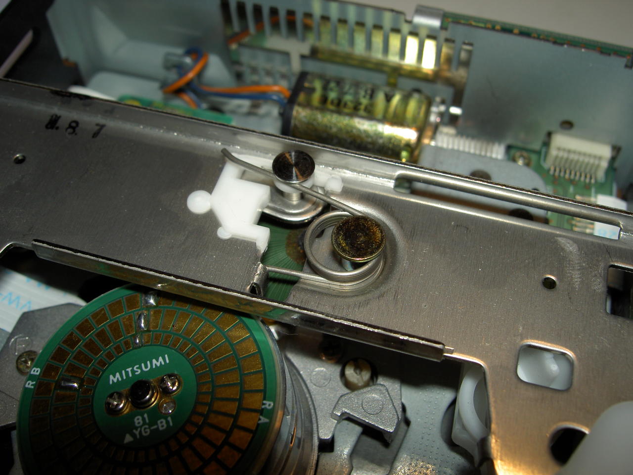
(Click to enlarge)
There is another small spring rear/right, put it out of the cartridge movement mechanics too.
Now remove the six guidance screws on the sides:

(Click to enlarge)

(There are sleeves on this screws, Click to enlarge)
Note: For reassembly remember the function of this lever on the
right side:
(the lever must later be reinserted in the keyway that is part of the drives metal base plate)

(Lever to open cartridge flap. Click to enlarge)
Now push the two plastic levers levers (as if a cartridge would
be inserted) to unlock the cartridge holder and push it inwards.
Then try to get the bolt on the left/front side out of its keyway
by pushing it to the front with a screwdriver.
Now lift the cartridge movement mechanics (left side first) while
getting the big bolt on the rear (where the spring was removed) out
of it.
Then remove the mechanics as a unit.
My drive already shows damage to some plastic covers:

(Click to enlarge)
If something desintegrates by accident, here are some pictures how the
spring inside must be mounted:

(Click to enlarge)

(Click to enlarge)
Now you should have a free view to the top of the drive mechanics:

(Click to enlarge)
To remove the metal back plate, remove the 3 screws on its bottom side
and pull it out of the drive rearwards.
(Click to enlarge)
The board on the back plate automatically disconnects.
Now remove the metal clip behind the DC motor.
Note if you have never disassembled such a drive:
There is an important screw hidden under the DC motor!
This means it is impossible to remove the drive from the plastic
chassis when the DC motor is left in place.
To remove the DC motor, remove its 2 screws:

(Click to enlarge)
Because the motor cables are soldered to the
"CAESAR MODE PCA" board, remove it too:
(Note: There are four identical screws for this group, one is missing in the picture)

(Click to enlarge)
This board contains two light barriers and a 24C16 EEPROM, both unrelated to the DC motor.
The next important step is the separation of the two main units of the
drive:
The drum unit, the tape guidance bolts and some other components
are mounted on the metal plate.
The rest of the drive is mounted on the plastic chassis.
Remove this two plastic snap rings:
Important: Do not break them or lose them!

(Click to enlarge)
I have used the small slotted screwdriver and the tweezers for this
difficult job.

(Click to enlarge)

(Click to enlarge)
Note: If one of the snap rings falls into the drive, you can turn
around and shake it
(the two units are still mounted together, nothing else will be
damaged or fall out).
To the right of the rubber roller (that pushes the tape against
the capstan) there is this group of parts:

(Click to enlarge)
Remove the screw and pull out the right plastic part.

(Click to enlarge)
Then slowly and carefully remove the other plastic part.
There is a sleeve and a spring under it, do not lose them!

(Click to enlarge)

(Click to enlarge)
Remove the plastic snap ring of the shaft on the bottom of the drive:

(Click to enlarge)
Then pull out the rubber roller from the top of the drive:

(Click to enlarge)
Note: The spring can be left in place.

(Click to enlarge)
Pull out the spring and pull out the cleaning lever:

(Click to enlarge)

(Click to enlarge)

(Click to enlarge)
Use a slotted screwdriver and turn the gearbox of the DC motor
(counterclockwise on the first wheel).
The lever that drives the cartridge movement mechanics will turn
backwards.
Stop if you can reach the screw on top of the shaft of the drum
cleaning roller!
Then pull out the spring:

(Click to enlarge)
Last remove the screw and pull out the drum cleaning roller:

(Click to enlarge)
If you see dust in the roller, remove it with the tweezers.
Put the drum cleaning roller on a clean surface, e.g. a piece of paper.
Open the connector for the foil cable of the drum unit.

(Click to enlarge)
Remove the three screws and pull out the board named "WRITE PCA":

(Click to enlarge)

(Click to enlarge)
Remove the screw and pull out the foil connector.
Then remove reflex light barrier group.

(Click to enlarge)
Now it's time to separate the metal base plate with the drum subunit.
First remove this plastic snap ring (left/back):

(Click to enlarge)
Then remove the screws left/front and middle/back (the one formerly
hidden by the DC motor) in the metal base plate:

(Click to enlarge)

(Click to enlarge)
From now on do not turn around the chassis anymore (otherwise the wheels will fall out of the gearbox)!
Should the gearbox ever desintegrate, look at the two holes in the
plastic chassis:
They must be both visible through the two black wheels (if their teeth
correctly match each other).
Attention: They must match because the middle black wheel controls
the light barriers on the "CAESAR MODE PCA" board!
Note: There are holes for both end positions of the gearbox.
The metal base plate can now be pulled out of the chassis:

(Click to enlarge)
Note: Should some of the mechanical parts fall out of the chassis, use the picture above to correctly reinsert them.
The white wheels can be inserted in any orientation:

(Click to enlarge)
Look for the sleeve that moves inside the keyway of the last wheel
in the gearbox (it adheres to the grease):

Remove the sleeve so that it doesn't get lost.
Then put the metal plate with the drum subunit on a clean surface, e.g.
a piece of paper.
For disassembly of the capstan and drum subunits, see the following pages:
Disassembly of drum subunit
Disassembly of capstan subunit
If you later reassemble the drive, mount the sleeve again.
Then check the gearbox. You need this setup:

Note: The drum cleaning roller is driven by the notch on the outside of the last wheel in the gearbox.
Now insert the sleeve at the outer end of the keyway in the last wheel
of the gearbox:


Reassemble the rest of the drive as described above (in opposite direction).